
An Introduction to 10 GHz
Wideband Operating in Ontario
(
| INTRODUCTION | WIDEBAND FM | EQUIPMENT |
| SOURCES OF PARTS | OPERATING TECHNIQUES | ACTIVITY IN AND AROUND ONTARIO |
| OPERATING SITES | PATH PLOTTING | GRID SQUARES |
| 10 GHz WBFM BIBLIOGRAPHY | ||
| The SHF Home Page | ||
This booklet is intended to offer the beginner to 10 GHz operation a general introduction to current practice in Ontario. It is not meant to provide complete technical details on how to build equipment, but rather to show what approaches are in common use and how the equipment is operated.
The 10 GHz band (10.0-10.5 GHz or 10000-10500 MHz) is one of the easiest microwave bands to get on, primarily as a result of its proximity to frequencies heavily used by various types of radars and the resulting equipment availability.
The most popular mode of operation on the amateur 10 GHz band in Ontario at present is wideband FM voice. By wideband, I mean the same bandwidth, more or less, as used by commercial FM broadcast stations. Typically this means about 75 kHz deviation and a receiver IF bandwidth of about 200-300 kHz. In practice this varies somewhat, depending on what equipment an individual amateur is using, but this is about the centre of the range.
This is a departure from the usual amateur practice on lower frequencies, where SSB and narrow band FM (about 5 kHz deviation) dominate for voice communication. These modes can be used at 10 GHz, but wideband FM allows the use of transmitters and receivers with relatively poor frequency stability. This means that equipment can be bought or built at much lower cost than would be needed for the more usual narrow band modes.
What do we give up by using wideband FM and simple equipment ? There are basically two things: (1) the poor frequency stability of the equipment means we can not just switch on the rig and be ready to communicate on a precisely defined channel, as we do on 2m FM, for example, and (2) the signals for a given power, antennas and distance, are not as strong as if we used a narrow band mode. However, the range can be surprisingly good at very low power levels.
Wide band FM activity in Ontario takes place mostly in the 10.200 - 10.400 GHz range.
Virtually all wideband FM equipment for 10 GHz can be described by the block diagram of Figure 1. The transmitter consists of a tunable oscillator (running directly on the transmit frequency) which is frequency modulated by the audio signal from the microphone amplified in a modulator circuit. This oscillator sends most of its output power to the antenna. A small portion of the oscillator power is coupled to a mixer, which is also coupled to the antenna. A 10 GHz signal received on the antenna arrives at the mixer and beats with the transmit oscillator frequency to give an output at a lower intermediate frequency (IF). The signal at the IF is then amplified, filtered, detected and then fed to an audio amplifier and speaker or headphones.
This is basically all there is to the transceiver. The differences between various rigs are in the following areas:
-device used in the 10 GHz oscillator (Gunn diode or Klystron tube)
-modulator circuit used
-how the power is coupled between the oscillator, mixer and antenna
-design of the IF strip
-whether any extra gadgets (such as automatic frequency control or a tone oscillator ) are used.
-the oscillator (transmitter) output power (normally 5-200 milliwatts)
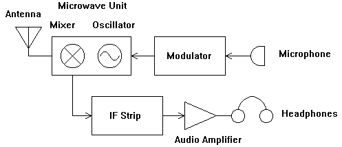
Figure 1: Block Diagram of 10 GHz Wideband FM Transceiver
Wideband FM transceivers for 10 GHz have no transmit/receive relay or other switching. They transmit and receive simultaneously and so a QSO using one is much like talking on the telephone. If signals are strong you will soon find yourself forgetting about things like saying "over"; it is much more like a normal conversation than most amateur radio operation is. To be able to do this, and with very simple equipment, there is one peculiarity. That is, the transmit and receive frequencies for a transceiver are not the same, and two transceivers in contact with each other must transmit on different frequencies.
For example let's assume that station A has his oscillator tuned to 10.300 GHz (10,300 MHz). He is then able to transmit an FM signal at this frequency. But the oscillator is also used as the local oscillator for the receiver. If station A has an IF of 100 MHz, then he can receive stations on 10.3 GHz +/- 100 MHz. In other words, if the transmitter is tuned to 10.300 GHz, the receiver is automatically tuned to both 10.200 GHz and 10.400 GHz. Now if station B wants to make a contact with station A he can tune his oscillator to 10.200 GHz. If he points his antenna at station A, then (given a good path between them) he will be heard at station A. But if he wants to hear station A transmitting on 10.300 GHz he must have his IF at 100 MHz; he will then receive on 10.100 and 10.300 GHz. This is one of the odd things about 10 GHz wideband FM operation...both stations must have the same intermediate frequency in order to work full duplex.
It is possible to make contacts when the stations involved have different IFs but it is much more difficult. More on this in chapter 6.
The preferred IF in southern Ontario is 30 MHz. This is a North American standard, resulting from the initial popularization of 10 GHz with the Gunnplexer systems sold by Advanced Receiver Research. The second choice is 90 MHz (approximately), for those using FM broadcast receivers as IF strips. In the UK, 10.7 MHz is commonly used, but it is rare here.
The transmission line of choice at 10 GHz is usually rectangular waveguide. It has much lower loss than any kind of coaxial cable that is suitable for this frequency. The most common size of waveguide for 10 GHz is usually called WR90 (in North America). This stands for "Waveguide, Rectangular, 0.90 inch". It is also known as WG16 in the U.K., IEC R100, and by the U.S. military designations RG-52/U and RG-67/U. It is a hollow metal tube with a rectangular cross-section of 0.90 by 0.40 inch (inside) and 1.00 by 0.50 inch outside. It is intended to operate from 8.2-12.4 GHz. It is probably the most common waveguide to be found on the surplus market because it has been used in many pieces of radar equipment since the middle of the Second World War. Intruder alarm modules usually have standard flanges for WR90 waveguide. The most common flange for connecting two pieces of waveguide together is nearly square with four holes for bolting the flanges together. The holes will either be tapped 8-32 or be clearance holes for 8-32 screws.
In this section I will describe several rigs which have been used in 10 GHz operations over the last few years. Some of these are completely commercially built rigs, either intended for amateur operation or for other purposes. Others are more or less home-brewed. They are:
- the Tellurometer: a South African distance measuring device for surveyors, which tunes from 10.05 to 10.45 GHz and has a voice facility so the surveyors could talk to each other. Many of these have been available on the surplus market but beware, there are versions for other (non- ham) frequencies too.
- the ARR TR10GA: a complete transceiver intended for amateur use.
- a typical homebrew rig based on a SOLFAN "double mount" intruder alarm module.
- a typical homebrew rig using separate Gunn oscillator and mixer modules.
The Tellurometer uses a Klystron tube as the 10 GHz oscillator. I have included it, although it is rather out of date, because of its availability. Individual klystrons are also occasionally seen at flea markets and in surplus electronics stores, but I have not described a home brew rig based on one. This is because it is considerably more difficult to build and adjust than a more modern solid state rig. I don't know of anyone who has built a klystron rig in the last 20 years
There is a picture of Ralph, VE3BBM, operating one of these on the front cover of the July/August 1989 issue of TCA. They were originally intended as surveying instruments. With a pair of them, it is possible to accurately measure the distance between two points using a link at 10 GHz. More usefully to amateurs, however, the designers included a voice communication capability and a telephone-like handset.
The 10 GHz oscillator is a klystron tube, mechanically tunable from about 10.050 GHz to 10.450 GHz with a turns counter for relative frequency readout. The klystron can be FM modulated by the audio from the handset microphone. The deviation is larger than normal for amateur use, perhaps about 150 kHz, but it can be copied on other rigs if the operator talks softly. A small dish (around 10 inches in diameter) is built in to the unit, and the power (a few tens of milliwatts) from the oscillator feeds this dish through a short piece of waveguide with 45 degree slanted polarization. A mixer diode mounted near the dish focus is set up to receive signals with the opposite slant polarization. Because the oscillator and mixer are cross-polarized, only a little of the oscillator power is coupled to the mixer diode. This method of coupling the power from the oscillator to the antenna and from the antenna to the mixer without putting too much transmit power into the mixer is often referred to as a "polaplexer". The mixer feeds an IF amplifier and FM detector operating somewhat above 30 MHz. The detected output is amplified (not quite enough, according to some owners!) and provided to the earpiece in the handset. There is an automatic frequency control circuit to lock the klystron to follow the frequency drift of the incoming received signal.
The power needed for the rig is obtained from a 12 V source. However, an internal inverter is used to obtain the high voltages needed to run the klystron. Everything else is solid state. It takes quite a lot of current from the supply (more than 1 amp, I believe).
If you find a Tellurometer at a flea market or surplus store, be sure to determine if it is the 10 GHz kind, or for some other frequency band. The 10 GHz version that I am most familiar with has about a 10 inch dish with a feed which is made (at least partly) of WR-90 waveguide.
This is the only commercially manufactured 10 GHz amateur wideband FM transceiver that I am aware of. It consists of a MA/Com Gunnplexer microwave unit and an IF/modulator board packaged in an attractive case with all the controls and connectors needed in a complete rig. A small horn antenna is normally supplied with the transceiver. It is sold by Advanced Receiver Research (ARR) of Burlington, Connecticut. A block diagram of the TR10GA is given in Figure 2.
The Gunnplexer consists of a varactor-tuned Gunn diode oscillator, a mixer diode and a circulator in a small assembly (a bit smaller than a 2 inch cube). A circulator is an extremely clever gadget. It has three connectors (or equivalent, such as waveguide). The antenna is connected to one, the oscillator to another, and the mixer to the third. The effect of the circulator is to cause nearly all the oscillator power to be directed to the antenna and only a little to the mixer; at the same time nearly all the power received on the antenna from a distant station is directed to the mixer, and only a small amount goes to the oscillator and is lost. The Gunn diode oscillator runs from a regulated 9 volts, and is tuned by varying the voltage on a varactor (variable capacitance) diode mounted in the oscillator's resonant cavity. A 10 GHz Gunnplexer can be tuned this way over at least 60 MHz and often as much as 100 MHz. The oscillator is frequency modulated by superimposing a small audio signal from the microphone on the varactor tuning voltage. ARR supplies Gunnplexers with the centre of the tuning range at either 10.250 or 10.280 GHz.
The IF/modulator board contains the circuitry needed to provide the tuning and modulation voltage to the varactor, the 9V regulator for the Gunn diode and a 30 MHz IF strip. The IF receiver is a superheterodyne, with a crystal controlled converter down to a 10.7 MHz IF, where the signal is amplified and detected in a CA3189E IC, originally designed for FM broadcast radios. An audio amplifier provides plenty of sound through headphones or speaker. Two meters display the varactor tuning voltage (or discriminator output voltage) and the signal strength. There is also a squelch function and automatic frequency control to lock the Gunn oscillator to follow the frequency of the incoming signal.
Both the Gunnplexer and the IF/modulator board (model RXMR30VD) are available separately from ARR for those who want to do their own packaging.
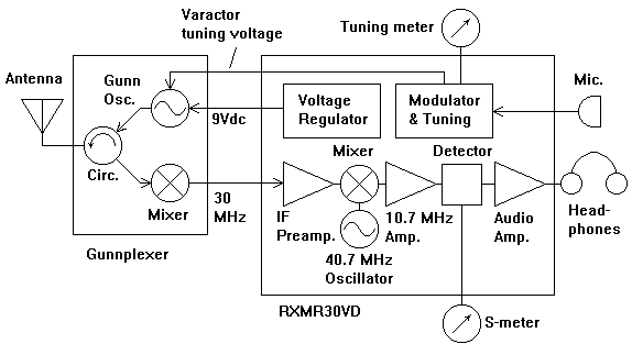
Figure 2: Simplified Block Diagram of TR10GA Transceiver
Perhaps the most common type of (more-or-less) home brew transceiver is based on the microwave unit from an intruder alarm made in large numbers by SOLFAN. These were in wide use all over North America until recently. They have been removed from use in large numbers during the 1980's and have been quite available from surplus outlets and sometimes from alarm companies, usually for $5 - $30. The most useful type has a cast body including a Gunn diode oscillator (without varactor tuning) and a mixer diode in the waveguide between the Gunn oscillator and the output flange. Similar microwave units are made by other manufacturers. Probably the most common on the surplus market are made by Alpha.
The Gunn oscillator will run from a voltage of about 6 - 9V (positive with respect to the case), at about 100 mA. Normally, the power supply for the Gunn is set up to have the voltage variable over about this range which has the effect of varying the frequency of oscillation by up to 40 MHz or so. The audio signal from the microphone is amplified and added to the power supply voltage to provide FM modulation. These power/tuning/modulation functions can be done with a simple circuit of as little as two ICs, which is all that is really needed in addition to the SOLFAN microwave unit to make a functional transmitter. See Figure 3 for a block diagram. Often, a tone oscillator is also provided, which can provide an alternative audio modulation signal (instead of the microphone) for tuning or for Morse operation when signals are weak. The output of the intruder alarm units is usually about 5 - 10 mW at 10 GHz. In alarm operation they are normally tuned to about 10.525 GHz and must be retuned into the amateur band before they can be used for communication. This is usually easily done, providing a frequency measuring instrument is available (see section 4.3).
On the receive side, the mixer diode terminal is connected (usually through a piece of coaxial cable) to a low noise preamplifier. This feeds an IF receiver. Some of the options for this receiver include:
-an FM broadcast radio, usually tuned to about 90 MHz. Car radios are good, but the modern synthesized type can be more difficult to use than the older ones with continuous tuning.
-a modified FM broadcast radio, with the front end rebuilt to receive 30 MHz, the preferred IF. I have one rig with two selectable circuit boards from FM stereo receivers, one "as is" and one converted to 30 MHz. The stereo decoder and audio sections were literally sawn off and a simpler audio amplifier substituted.
-a homebrew receiver based on the Philips TDA7000 "FM radio on a chip" IC, which can be used at either 30 or 90 MHz. An LM386 IC makes a good audio power amplifier.
-a somewhat more complicated homebrew superheterodyne receiver with 30 MHz input and a 10.7 MHz second IF, usually employing a single chip IF/detector IC such as a CA3089E, CA3189E, ULN2111, etc.
Normal practice is that 30 MHz IF strips are fixed-tuned, but 90 MHz IFs are tunable to allow the operators to select a frequency not subject to break-through interference from local FM broadcast stations.
Keep in mind that the standard is wideband FM, so an unmodified 10m FM transceiver or narrow band FM scanner is not suitable for the IF receiver.
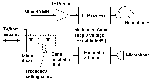
Figure 3: Block Diagram of Transceiver using SOLFAN Dual-Mount Microwave Head
Separate Gunn diode oscillators are also frequently available as surplus, including alarm units from SOLFAN and others, and higher power oscillators from police speed radars can sometimes be found. The best way to use these to build a transceiver is to acquire a circulator and a waveguide detector/mixer unit (see also section 4.2). When connected as shown in Figure 4 the bulk of the oscillator signal will go to the antenna and the most of the power of any signal received by the antenna will be directed to the detector (in this case used as a mixer). Since these various pieces are not usually designed to operate together, a good check is to measure the current from the mixer diode terminal to the case; it should be somewhere in the range of 0.2 - 2 mA, for best operation. The modulator and IF circuits can be the same as described in the previous section.
If you manage to acquire a higher power Gunn oscillator, say in the 100-200 mW output range, there are some additional points to consider. Usually the supply voltage for such devices is a little higher, often 10-12 V, so you may not be able to use a 12V battery to run a simple variable supply tuning/modulator unit as some voltage drop will be needed to make it work. Also, never short the waveguide output from the circulator (the antenna connection). If you do, all the oscillator power will be reflected back into the circulator and, since it is apparently coming from the antenna, will be directed to the mixer. This power level can be enough to burn out the mixer diode.
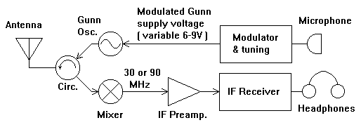
Figure 4: Transceiver Using Separate Gunn Oscillator and Mixer
Horn antennas are simply tapered waveguide sections. If the length of the taper is sufficient for the size of the horn aperture, the energy will be nearly in phase over the aperture, which results in higher gain than from a piece of open WR-90 waveguide. Such an antenna also has the advantage of being very broadband and having low VSWR, so long as the taper is sufficiently long and the walls are smooth (no sharp steps).
The gain available runs from about 6dBi (for open waveguide) to about 24 dBi. Horns can be made with larger gains but the required length of the taper begins to increase extremely quickly and soon becomes impractical. Often, SOLFAN and other alarm equipment is obtained with small horn antennas attached. These are great for initial testing but are generally not adequate for long distance work. Advanced Receiver Research sells 17 dBi gain horns which are typically good for some tens of kilometres (more if the station on the other end has a bigger antenna). It is not too hard to make horns out of double-sided PC board material or sheets of hobby brass or galvanized iron. Some of the articles in the bibliography describe how to make them. Many people find the layout of a pattern for cutting the horn parts to be the hardest part; a knowledge of trigonometry is useful, although trial-and-error also works.
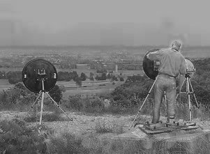
The "standard" antenna for 10 GHz wideband FM stations all over North America seems to be a parabolic reflector ("dish") about 2 feet in diameter. Most have been obtained from surplus sources although occasionally US suppliers of new dishes with reasonable prices can be found. Dishes have (usually) higher gains than horns, ranging from about 20 dBi for a 6 inch diameter reflector to about 40 dBi for a 5 foot diameter dish. Dishes smaller than 6 inches are too small to work well and anything larger than 5 feet has such a small beamwidth that it is very difficult to aim; so this is about the range of sizes that is actually used. The beginner is advised not to start out with a dish much more than 2 feet across until some experience in aiming the antenna is gained. Most reflector antennas in use by amateurs are of the symmetric type, although a few have tried offset reflectors such as those used for Direct Broadcast Satellite TV reception.
Most 10 GHz FM operation is by portable stations who normally use some
sort of tripod to support the antenna and at least some part of the
electronic part of their equipment. Most common are camera tripods, with the
screw removed or with an adapter to fit it built into the antenna. Very
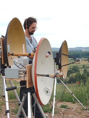 inexpensive
camera tripods are adequate for horn antennas but for a 2 foot dish, a
medium to heavy duty tripod is required. It is useful to have a pan/tilt
head to allow the antenna to be steered in both azimuth and elevation.
However, if necessary, the elevation control can be had by adjusting or
moving the tripod legs. Surveyors' tripods are also excellent, being heavy
duty and tall (good for getting the signal over walls, fences, hedges,
etc.). They normally need some sort of modification to mount antennas,
rather than the standard mount for theodolites, etc. A simple homebrew
tripod can be made quite cheaply, by connecting three 4 foot long legs (1
inch dowels or 1x2 inch lumber) to a top plate a few inches across using
hinges. A bolt through the top plate provides a pivot for azimuth rotation.
One practical word of caution regarding dishes and tripods: they blow over
easily in a wind. On a windy day you will need to find a way of guying the
tripod or you must stand beside it at all times to prevent it from toppling.
inexpensive
camera tripods are adequate for horn antennas but for a 2 foot dish, a
medium to heavy duty tripod is required. It is useful to have a pan/tilt
head to allow the antenna to be steered in both azimuth and elevation.
However, if necessary, the elevation control can be had by adjusting or
moving the tripod legs. Surveyors' tripods are also excellent, being heavy
duty and tall (good for getting the signal over walls, fences, hedges,
etc.). They normally need some sort of modification to mount antennas,
rather than the standard mount for theodolites, etc. A simple homebrew
tripod can be made quite cheaply, by connecting three 4 foot long legs (1
inch dowels or 1x2 inch lumber) to a top plate a few inches across using
hinges. A bolt through the top plate provides a pivot for azimuth rotation.
One practical word of caution regarding dishes and tripods: they blow over
easily in a wind. On a windy day you will need to find a way of guying the
tripod or you must stand beside it at all times to prevent it from toppling.
Other support methods can be used. For small rigs with horn antennas the top of a car, or the tailgate of a truck or hatchback, or a small folding table, can be used. I have even seen VE3MNA making contacts with a 2 foot dish held under his arm. It worked well but is not recommended to the beginner !
If you live on a hill and want to try 10 GHz from home, with a tower-mounted antenna, there are a couple of things to keep in mind. With a horn antenna, any normal rotator will work well. However, with a dish of 2 feet or so, it will become somewhat difficult to aim using a HAM-M type rotor, due to the narrow beamwidth. Also, the force due to wind on the dish can be considerable, so ensure that the structure is adequately strong.
The first nearly indispensable piece of test equipment I will mention is a signal source for testing your receiver. The easiest to find is a Gunn oscillator, which can be found from time to time at surplus stores or at flea markets and hamfests, usually for $5 - $10. You may also be able to convince an alarm company to give or sell you one or more from the units they have taken out of service. For the purpose of generating a signal to listen to, you don't need the mixer diode, so a Gunn-only type will be entirely satisfactory. You will probably want to equip it with a modulator of the type used in a transceiver so that you can produce a modulated FM signal to listen to on your main transceiver. Of course, once you start down this road you will probably end up with another complete transceiver before long, which is an even better piece of test equipment.
Surplus commercial signal generators that cover the 10 GHz band are also to be found occasionally, though they will cost you much more than a Gunn oscillator.
A waveguide mounted RF detector is extremely useful to have. The obvious purpose is to find out if there is any output from your transmitter (or test source). It can also be used with an absorption wavemeter to measure your transmit frequency or as a "Boomerang" (see 4.4). There are 3 main options here.
1.You can use the mixer diode in a Gunn/mixer alarm unit as a detector. Just connect a microammeter to the terminal and to the waveguide body to get a readout. Be careful of static electricity...it can burn out the mixer diode in an instant.
2. Use a surplus WR-90 waveguide detector mount. Usually these have 1N23 type or similar diodes in them which are easily replaced if you zap them (if you can find a supply of diodes!). Use it the same way as #1. These usually have a BNC connector for the output voltage. Surplus price is often about $10. Sensitivity of surplus detectors varies considerably, due to the use of different detector diodes and because the devices may not be tuned for best response in the amateur band.
3. Use a waveguide to coaxial transition and a coaxial detector. Coaxial detectors that work up to 10 GHz are not that common (because they are often still useful to industry and government) but they do show at hamfests and in surplus stores occasionally. The waveguide to coax transition will normally have either an N-type or SMA fitting, never BNC. Use it the same way as #1.
This is a very useful gadget. It is essential if you are going to use surplus Gunn oscillators that you have (or have access to) a frequency measuring instrument. If you know someone with a frequency counter that works at 10 GHz, use it. However, most of us are stuck with the older technology of absorption wavemeters. The wavemeter consists of a piece of waveguide (or coaxial cable) with flanges or connectors on both ends, coupled lightly to a precisely tunable resonant cavity. You put microwave power in one end and a detector at the other end. As you tune the cavity through the frequency of the microwave signal, you will notice a drop in the power detected, as some of the power is sucked into the cavity and absorbed in its walls.
These units are available from time to time in the usual surplus channels (flea markets, surplus electronics outlets). The best are the Hewlett Packard X532A or X532B models which have WR-90 waveguide interfaces and cover 8.2-12.4 GHz with an accuracy of +/-8 MHz or better. These typically sell as surplus for $50 - $100. There are other manufacturers, as well. It is also possible to modify and recalibrate the wavemeters from the military TS-147 radar test set which normally tune a range just below the ham band. I found one (just the wavemeter) in a surplus store for $25 a few years ago.
The so-called boomerang consists of a waveguide detector, perhaps with a small horn antenna connected to the waveguide flange, and with a low power (up to a few milliwatts) signal generator tuned to your transceiver's IF connected to the normal detector output connector. It is used to check both the transmitting and receiving capabilities of a wideband FM transceiver, as follows. Set the device up a few feet from, and pointing at, the transceiver' antenna. Switch on the transceiver and the signal generator attached to the detector. The transceiver will emit a signal at frequency f
TX which is then received by the boomerang. In the waveguide detector diode it will mix with the signal generator frequency fIF to produce two new signals at fTX +/- fIF. These signals are then radiated back toward your rig and, since they differ from the transmit frequency by the IF, they can be received. This allows you to monitor the sound of your transmitted modulation.Commercial outlets listed below are not necessarily endorsed by the author. As always, let the buyer beware !
Advanced Receiver Research, Box 1242, Burlington CT 06013, USA. Tel: (860) 485-0310
(TR10GA Transceiver, Gunnplexers, IF/Modulator Boards, Antennas, Gunn/varactor/mixer diodes)
These are the surplus outlets I know of in Ontario where you may be able to find microwave goodies.
-Electronic Surplus Industries, Lawrence Ave.W (at Caledonia), Toronto (often has WR90 waveguide stuff)
-W.J.Ford Surplus, 21 Market St., Smith's Falls
- A source for sporadic Microwave stuff is Cohen and Cohen located on Merivale Road (near Slack Road) in Ottawa. (tnx to Janusz, VE3ABX) .
-Toronto Surplus and Scientific, Gordon Baker Road, Toronto (Willowdale) (lots of good, but not particularly cheap, test equipment)
-Active Surplus, Queen St.West, Toronto (occasionally have some microwave stuff)
-Horizon Electronics, Frederick and Victoria St. N., Kitchener
SHF Parts in Indiana usually has a selection of Gunn oscillators and intruder alarm microwave heads. A few parts useful for WBFM can be obtained from Down East Microwave Inc. in New Jersey. Other suppliers exist; they tend often to be "one-man shows" or part-time basement businesses which can come and go in a short time or have limited stocks.
Alarm companies are a variable lot. Microwave intruder alarm units are no longer held in very high regard as they are apparently prone to quite high rates of false alarms. What the companies do with units that are taken out of service ranges from throwing them out to actually giving them to radio amateurs. It depends on the individuals at the local offices, it seems. It is certainly worth giving them a call to see if they would be willing to sell or give you old units. Tell them the whole story of what you want to do with them so their fears that they may be giving equipment to start-up competitors will be reduced. Certainly several Ontario amateurs have been able to acquire numbers of units at very reasonable cost.
Try your local amateur radio flea markets. You never know what you might find. If you want to venture further afield, the annual hamfests in Dayton, Ohio and Rochester, New York (both in May) are probably the among the best places to find microwave parts.
Most 10 GHz wideband FM operating is done with portable equipment at locations away from home. This is because good high locations are needed to be able to make contacts over long distances with this simple equipment.
 Selecting
Operating Sites
Selecting
Operating SitesA good operating site is usually one with a spectacular view. Paths that can normally be worked are only slightly longer than one can see from the operating site. Just as they do for your view of the scenery, buildings, trees, and so on block the signal. Except for the shortest of paths, the takeoff in the direction of the other station must be clear of such obstacles.
6.3.1 When the Other End is Visible
If the operator at the other end of the path is located at a clearly
visible landmark such as a ski hill or a tall building then you merely need
to aim your antenna by eye at the landmark. A pair of binoculars or small
telescope can be very useful in identifying less obvious objects, such as
individual houses or communications towers. Don't forget that if you are
using a dish of a foot or more in diameter, it will likely be necessary to
aim in both azimuth and elevation to get the best signal.
If the weather is not clear, there are no landmarks to sight on, or the path is beyond the horizon then other approaches are needed. A magnetic compass will be found to be nearly indispensable. A toy compass will not normally offer the necessary accuracy; a sighting compass of some sort will be needed. A number of types are available, the most common being the type sold for orienteering and the "lensatic" compass, both of which are quite satisfactory. Reasonably accurate bearing information can be obtained using a protractor and a ruler on a map (preferably a topographic map). Don't forget to add the amount of the magnetic declination to the True bearing obtained from the map to get the magnetic bearing you will aim the antenna along. For example, from the map you may determine that the other station is located to your north-east (True Bearing of 45 degrees). The magnetic declination in your area may be 10 degrees (typical of much of southern Ontario in the 1990s), so the bearing you will need to read from the compass is 55 degrees.
A good map may also yield other approaches to finding the path bearing. One way that is quite often useful is to find a bearing with respect to a road you are on. If the path is just a few degrees off the direction of the road, or nearly perpendicular to the road, you can likely get the antenna pointing quite close without a compass or other instrument. The author has also used an easily constructed version of the "cross-staff", a medieval navigational instrument, to find bearings with respect to nearby or clearly visible landmarks.
It is rare to be able to make a contact on 10 GHz either randomly or without some real-time coordination between the operators involved in a scheduled contact. Usually, the operators will coordinate their frequency settings, antenna bearings, etc. on 2m FM. The frequencies most often used in southern Ontario and western New York are 146.55 and 146.58 MHz simplex. However, if the 2m equipment is not sufficient for direct contact, any available repeater may be pressed into service. Because of the unusual nature of the communications, it can be difficult to use a repeater for talkback if there is any other activity on the frequency, so simplex is preferred.
Surprisingly, it is not uncommon for the 2m simplex path to be difficult or impossible to work with mobile or handheld rigs running a few watts, but when everything is finally set up on 10 GHz, the microwave signals (with only a few milliwatts) are excellent, full quieting quality ! For this reason it is advisable to have available a small 2m beam if paths much more than 50 km are to be tried.
Especially if there is 10 GHz narrow band (SSB,CW) activity under way, there may be talkback activity on 2m SSB. 144.200, 144.260 and 144.300 have been used in recent years.
There are two fundamental propagation modes that are useful for 10 GHz wideband FM. These are line-of-sight and tropospheric ducting. In fact, when the term line-of-sight is used for microwave propagation it usually implies that the small average amount of tropospheric ducting that is normally present is factored into the expectations of whether a path can be worked or not. Thus, a microwave line-of-sight path, during average conditions, can be slightly further than can actually be seen, say with a telescope. The beginner, however, will do well by starting off with truly optical line-of-sight paths as they will tend to be less variable from day to day. While paths slightly over the optical horizon will often work well, local obstructions near either end of the path can eliminate any chance of a contact. A building, or even a single tree in the direction of the other station and within a few hundred metres of one end of the path, is usually enough to drop the signal below the detection threshold. Short paths which are blocked in this way can occasionally be worked by a reflection path, where both stations aim their antennas at a large object visible at both ends. In southern Ontario, the longest paths workable by line-of-sight propagation are a little more than 100 km in length. If only we had some real mountains!
Under typical conditions, stations with 2 foot dishes and 10 milliwatts can work each other over any line-of-sight path in southern Ontario. With horn antennas some of the longer paths may be more difficult.
Tropospheric ducting is the propagation mode responsible for distant UHF TV reception and the "lifts" often experienced on 2m, mostly in the summer and fall. To be useful for 10 GHz, the ducts must form at ground level (so the antennas will be in the duct). Reception of distant UHF TV stations at much better than normal signal strengths appears to be a good indicator of these ducts. It tends to be difficult to make good use of them for 10 GHz wideband FM because they usually happen at night and early in the morning, at which time you need to arrange with another ham to go to portable sites, probably more than 100 km apart to try for a contact. A 10 GHz-equipped home station at a good location may have a better opportunity. Contests offer a chance to be out there anyway, and if interesting propagation happens you will be ready. It is worth keeping in mind that a number of contacts of more than 1000 km in length have been made around the world using wideband FM and tropospheric ducting propagation.
It has been the experience of the active 10 GHz amateurs in southern Ontario that paths over the Great Lakes can be enhanced substantially at times, and conversely, over-water paths that are clearly line-of-sight can on occasion be unworkable with 10 GHz WBFM equipment.
6.6.1 Choosing Frequencies
In Ontario, the usual practice is to use nominal transmitting frequencies selected from a set of "channels" spaced 30 MHz apart. This practice is derived from the availability from Advanced Receiver Research of Gunnplexers with their nominal frequencies factory preset to 10.250 and 10.280 GHz. To maintain compatibility with these Gunnplexers, amateurs using other equipment usually set their Gunn oscillators to these frequencies or other frequencies separated from them by multiples of 30 MHz. The frequencies in common use are 10.220, 10.250, 10.280, 10.310, 10.340, 10.370 and 10.400 GHz. Stations using 90 MHz IFs will usually select frequencies from this list as well. There is no particular reason to pick a given frequency...just agree with the station you want to work on what frequencies to use. Sometimes, surplus Gunn oscillators designed for 10.525 GHz will not readily tune below 10.3 GHz or so, so in this case the higher frequencies must be used.
It is normally necessary to tune around a bit to find the other station's signal. As well, particularly if a dish antenna (rather than a horn) is used, the antenna must be rocked back and forth as well. The combination of tuning and antenna-turning can sometimes take several minutes to succeed, even if when everything is eventually peaked, the signals are full-quieting. For beginners it is probably best that only one of the two stations tune and turn the antenna at a time, while the other sets the Gunn frequency to the frequency agreed on (as accurately as he can). If this doesn't work, then you can trade roles and try again.
The capability of modulating the transmitter with an audio tone rather than voice can be very helpful when trying to establish contact. A continuous tone stands out from the background noise much better than intermittent speech. As well, if the tone can be keyed, a Morse contact can sometimes be successfully completed when the received signal is too weak to copy voice.
Simple Gunn oscillators are not overly stable in frequency as they warm up and with respect to variations in the temperature of the environment. Temperature changes (of the Gunn oscillator housing) due to the Sun being obscured by clouds or due to gusts of wind can be noticeable. M/ACOM Gunnplexers are rated for <250 kHz drift per degree (Celsius) of temperature change. The lower quality SOLFANs are probably worse. It is normally necessary to keep a hand on the Gunn tuning knob to keep the other station tuned in properly. A few amateurs in this area have automatic frequency control; that is, once a signal is received, their Gunn will be automatically locked to follow the drift of the received signal.
If the two stations trying to work each other have different receiver intermediate frequencies, then they will not be able to work in full-duplex mode. However, they can still work each other, if at least one of them has enough Gunn tuning range so that the frequency difference between their two oscillators can be set to be equal to either of the IFs. Then, when one station is transmitting, the Gunn is set so the frequency difference is equal to the IF of the receiving station. Then when the other station wants to transmit, one of the Gunns must be tuned so that the frequency difference between them is equal to the IF of the new receiving station. It is inconvenient and usually takes considerable setting up through the talkback rig, but it does work and can be quite smooth in operation with two operators who are accustomed to it.
There are seven North American contests annually in which contacts on 10 GHz are eligible for points. They are the best times to expect significant amounts of 10 GHz activity, but are not the best time to test a new rig, as the more serious competitors will be in a hurry and not too keen to help out in a long set of experimental adjustments.
The seven contests are:
-January ARRL VHF Sweepstakes: all bands from 50 MHz and up are eligible and contacts on the microwave bands are worth more points than on the lower frequencies. It's usually awfully cold for portable operation, so 10 GHz activity is rare. The contest exchange and multiplies are 4-character grid square so no complicated geographical calculations are needed.
-June ARRL VHF QSO Party: all bands from 50 MHz and up are eligible. Scoring is different from January but is still based on 4-character grid squares and awards extra points for microwave contacts. Stations in the Rover category frequently take 10 GHz gear along.
-June ARRL Field Day: all amateur bands are eligible. There are no extra points for microwave contacts. 10 GHz counts exactly the same as 40m. But it is a good excuse to show off something different to your local club members. There is usually no concentrated activity...you will have to set up contacts with a friend or two.
-July CQ World-Wide VHF Contest: all bands from 50 MHz and up are eligible. Scoring is based on 4-character grid squares and extra points are given for microwave contacts. There is very little activity in this contest in the Great Lakes region for some reason.
-August ARRL UHF Contest: all bands from 220 MHz and up are eligible. Scoring and exchange are similar to the June contest but with more points being given per contact. Without six and two metres, this one is a bit more relaxed and you have a better chance of obtaining the patient cooperation of other operators that is often needed for 10 GHz contacts.
-August/September ARRL 10 GHz and Up Contest: 10 GHz is the lowest and most popular frequency eligible for points in this unusual contest. It takes place over two weekends about a month apart from 8AM to 8PM local time Saturday and Sunday (expect a change of hours in 1999). This is really the big event of the year for many 10 GHz operators. Rules are very unusual, allowing repeat contacts over and over with the same station if each contact is a substantially different path. Exchange is the full 6-character grid square and score is based on distance worked, so you need to know where you are !
-September ARRL VHF QSO Party: Same rules as June.
For contest rules and results see QST magazine or www.arrl.org for the ARRL contests and Field Day and CQ magazine for the July contest.
Activity tends to be centred around a few areas with several particularly active amateurs. Over the past few years the region in Ontario with the highest concentration of activity have been in the southwest (London/Kitchener/Cambridge/Georgetown). However, other areas have also been represented, by operators based in and North of Metropolitan Toronto, the Ottawa area, Chatham, Stoney Creek, Burlington and Oakville, for example. For paths across the Great Lakes, there has been activity based in the Rochester, New York area and in the extreme westerly part of New York state. There is also an active group in the Montreal area.
The following list of amateurs in Ontario includes most of those known by me to have been active on 10 GHz WBFM in the last few years, either with their own, or borrowed, equipment:
VE3ASO (silent key) Dennis, Mountain
VE3AX Peter, Cayuga
VE3BBM Ralph, Nepean
VE3BFM Bob, Everett
VE3EWP Bob, Cambridge
VE3EZP John, London
VE3FAC Richard, Scarborough
VE3FHM Graham, Georgetown
VE3HJK Rob, Oakville
VE3KDH Kevin, (then in Burlington)
VE3LPP Bruce, (then in Cambridge)
VE3MNA Mark, formerly in London, now Tobermory
VE3MWM Stu, Burlington
VE3OCY Don, Stoney Creek
VE3OIK Bob, Kitchener
VE3OIL Russell, Freelton
VE3OVY Kevin, (then in Cambridge)
VE3PFC Don (then in Cambridge)
VA3REI Reinhart, Waterloo
VE3RKS Roger, Waterloo
VE3SJV John, Baden
VE3SMA Steve, Cambridge
VE3TCK Ed, Waterloo
VE3TIL Scott (then in Kitchener)
VE3TJD Ted, Baden
VE3UX Dennis, Chatham
VE3VWO Mike,Port Colborne
VE3VXO Joe, Waterloo
VE3WCB Clarke, Milton
VE3XCW (silent key) Al, Oakville
VE3YOC Mary, Stoney Creek
VE3ZXN Dennis, Toronto
A list of operating sites in and around Southern Ontario is provided on the following pages. Most of these sites have actually been used for 10 GHz or other microwave contacts. There are doubtless many more good sites that have not been identified yet.
To determine if a given path between two locations is likely to work on 10 GHz wideband FM it is useful to plot the path that the signal will take with respect to the hills and valleys between the two sites. If the signal must pass through a large hill, then the path is unlikely to be workable. There are three approaches:
(1) take measurements of distance and height of the intervening land from a topographical map and plot on special graph paper which accounts for the curvature of the Earth and the typical tropospheric refraction effects. Samples of these graphs are given in the book by Saveskie. See section 11.7.
(2) plot the same data on ordinary graph paper, but after applying some simple formulas to transform the Earth into a flat surface and the line-of-sight into a curve ! This is actually quite easy and is described in the articles by N7DH listed in 11.7.
(3) use a computer program. Several are available but I have no references for them. I made up an EXCEL spreadsheet for my own use to perform calculations by N7DH's approach.
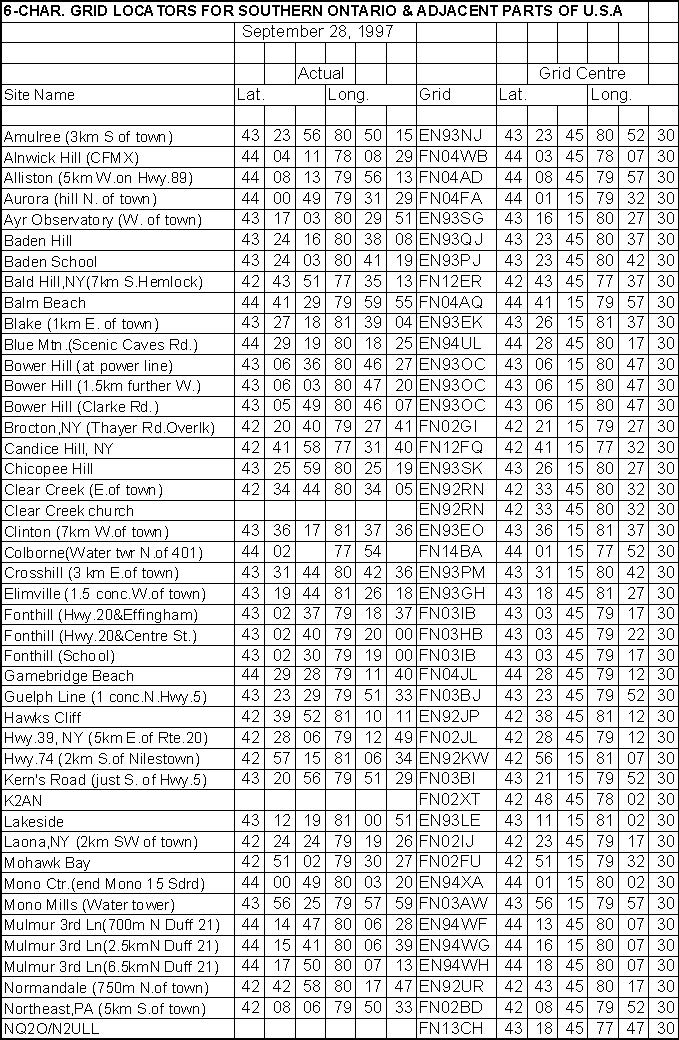
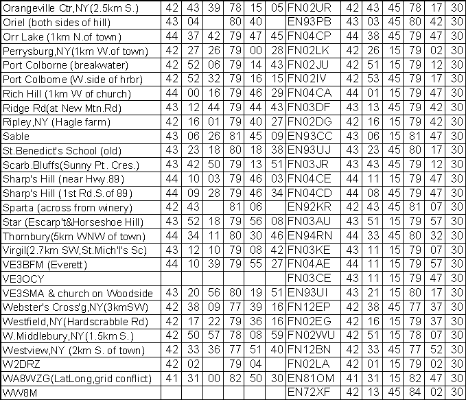
The "Maidenhead Locator" system is a worldwide system of coordinates that allows a location on the Earth to be defined in a few characters, somewhat more briefly than using latitude and longitude numbers. It is used as an exchange in most VHF (and up) contests. It is a bit complex to explain here; the references in Section 11.8 should be consulted. The ARRL and other organizations publish maps showing the "4-character grids" which are the intermediate level of accuracy in this system. The 10 GHz-and-up contest uses the more accurate 6-character sub-squares; you will need to consult a topographic map or a Global Positioning System receiver to determine your location accurately enough to know which of these sub-squares you are in. The six character locators for some operating sites are given in the table on the following pages
This list contains any references related to 10 GHz wideband operation that I am aware of. It is by no means complete. This section is sorted into several categories according to the main subject of the article. Within each section the articles are in no particular order. There are many more articles that pertain to narrow band operation on 10 GHz which are not listed here. I have not attempted to put together any information on World Wide Web sites dealing with amateur 10 GHz operation, but there are a number of interesting ones, often dealing with operating and operators, rather than technical details.
Michael Ross, VE2DUB, "Microwaves", TCA, December 1984 (description of ARR TR10GA)
Michael Ross, VE2DUB, "Microwaves", TCA, March 1986 (description of Mutek GDIF 107ub IF/Modulator board)
A.Wakeman, G3EEZ, "A simple 3cm polaplexer", Radio Communication, November 1970 (in case you still want to try a Klystron !)
Klaus H.Hirschelmann, DJ7OO, "10-GHz transceiver", ham radio, August 1978
James R.Fisk, W1HR, "Low-Noise 30-MHz Preamplifier", ham radio, October 1978
Brian Dance, "IC of the Month - RCA CA3189E FM Device", Practical Wireless, November 1978
James R.Fisk, W1HR, "10-GHz Gunnplexer Transceiver", ham radio, January 1979
Richardson, W4UCH/2, The Gunnplexer Cookbook, Ham Radio Publishing Group, Greenville, NH, 1981
Richard Bitzer, WB2ZKW, "Gunn Oscillator Design for the 10-GHz Band", ham radio, September 1980
Dick Ganderton, G8VFH and John M.Fell, G8MCP, "PW 'Exe' Microwave Transceiver", Practical Wireless, June/July/August 1981
Ed Sullivant, WB5MAP, "10 GHz ATV: The Easy Way", TCA, July/August 1985
Michael Ross, VE2DUB, "Microwaves", TCA, April 1986 (transceiver block diagram)
Michael Ross, VE2DUB, "Microwaves", TCA, June 1986 (IF circuits)
Michael Ross, VE2DUB, "Microwaves", TCA, July/August, 1986 (modulator circuit)
C.L.Chuck Houghton, WB6IGP, "Microwave Building Blocks, The Solfan Special", 73, January 1987
Michael Ross, VE2DUB, "Microwaves", TCA, April, 1987 (10.7 MHz preamp)
Larry Filby, K1LPS, "More on the 'Flavoradio' Receiver Conversion", in Proceedings of Microwave Update '91, ARRL, 1991
Kent Britain, WA5VJB, "Building Your Own 'Cheap' Doppler Radar", in Proceedings of Microwave Update '91, ARRL, 1991
Steve J.Noll, "Radar Detector to Microwave Receiver Conversion", 73, February 1991
(Various authors), "6.1 Gunn Oscillators", in The Microwave Newsletter Technical Collection, RSGB, 1984
D.Evans, G3RPE and C.Suckling, G3WDG, "A simple 10 GHz receiver with transmitter option", in The Microwave Newsletter Technical Collection, RSGB, 1984
G3YGF, "A Doppler Transceiver for 10 GHz", in The Microwave Newsletter Technical Collection, RSGB, 1984
G4KNZ/G3YGF, "Gunn Diode Power Supply", in The Microwave Newsletter Technical Collection, RSGB, 1984
G4KNZ/G3YGF, "A 10.7 MHz IF Preamplifier and Discriminator", in The Microwave Newsletter Technical Collection, RSGB, 1984
C.L.Houghton, WB6IGP, "Gunn and IMPATT Microwave Devices", 73, October 1987
C.L.Houghton, WB6IGP, "10 GHz Polaplexer Transceiver", 73, October 1988
"10-GHz Gunnplexer Communications", ARRL Handbook, 1990 Edition
"A High-Performance Audio Communications System", ARRL Handbook, 1990 Edition (gives circuit for Advanced Receiver Research IF/modulator board)
Chapter 8, "Microwaves", in RSGB VHF-UHF Manual , 3rd Ed. , Radio Society of Great Britain, London (or later editions)
Richard P. Banghart, "Chapter 4 - Microwave Devices", in The ARRL UHF/Microwave Experimenter's Manual , ARRL, 1990
Dr. H.Paul Scuch, N6TX, "Transmission Media", in The ARRL UHF/Microwave Experimenter's Manual , ARRL, 1990
William M.Brooks, WB6YVK, "A Fresnel-Zone Plate for 10.4 GHz", ham radio, May 1982
Dave Ingram, K4TWJ, "An Expandable Microwave Network for Multimode Communications", ham radio, August 1982
Michael Ross, VE2DUB, "Microwaves", TCA, January 1985 (basic how-to on parabolic dishes)
G3YGF, "Horn Antennas from Oilcans", in The Microwave Newsletter Technical Collection, RSGB, 1984
C.L.Houghton, WB6IGP, "Dishing it Out on 10 GHz", 73, September 1986
Margarete Ralston, KI4VE, "Design Considerations for Amateur Microwave Antennas" in Proceedings of Microwave Update '88, ARRL, 1988
Harold Reasoner, K5SXK, "Microwave Feeds for Parabolic Dishes", in Proceedings of Microwave Update '89, ARRL, 1989
Kent Britain, WA5VJB, "Horns for 10 GHz and Up", in Proceedings of Microwave Update '89, ARRL, 1989
Sam Popkin, K2DNR/7 and Kent Britain, WA5VJB, "A Simple Rectangular/Circular Waveguide Transition for 10 GHz", in Proceedings of Microwave Update '89, ARRL, 1989
Harold Reasoner, K5SXK and Kent Britain, WA5VJB, "10 GHz Slot Antenna", in Proceedings of Microwave Update '89, ARRL, 1989
Harold Reasoner, K5SXK and Kent Britain, WA5VJB, "10 GHz Omni-Directional Antenna", in Proceedings of Microwave Update '91, ARRL, 1991
Dick Turrin, W2IMU, "A Simple Dual-Mode (IMU) Feed Antenna for 10368 MHz", in Proceedings of Microwave Update '91, ARRL, 1991
Kent Britain, WA5VJB, "10 GHz IMU Feedhorn Update", in Proceedings of Microwave Update '91, ARRL, 1991
Jerry Jensen, WT0W, "An Inexpensive 10 GHz Dish System", 73, February 1991
Chapter 8, "Microwaves", in RSGB VHF-UHF Manual , 3rd Ed. , Radio Society of Great Britain, London (or later editions)
Bob Atkins, KA1GT, "Aiming Microwave Antennas", in The ARRL UHF/Microwave Experimenter's Manual , ARRL, 1990 (also includes info on bearing calculations)
Paul Wade, N1BWT, "Parabolic Dish Feeds - Performance Analysis", in Proceedings of Microwave Update '97, ARRL, 1997
Steve J.Noll, WA6EJO, "X-band Calibrator", ham radio, April 1981
G6XM, "A Gunn Diode and Oscillator Test Rig", in The Microwave Newsletter Technical Collection, RSGB, 1984
Charles Osborne, WD4MBK, "Basic Test Measurements and Test Equipment for the Microwave Amateur", in Proceedings of Microwave Update '88, ARRL, 1988
C.L.Houghton, WB6IGP, "Microwave Test Equipment for 10 GHz", 73, October 1988
Keith R. Ericson, K0KE, "Getting Started in Microwave Measurement", in Proceedings of Microwave Update '88, ARRL, 1988, and in The ARRL UHF/Microwave Experimenter's Manual , ARRL, 1990
Kent Britain, WA5VJB, "Waveguide Loads", in Proceedings of Microwave Update '89, ARRL, 1989
Kent Britain, WA5VJB, "Using WR-62 Waveguide on 10 GHz", in Proceedings of Microwave Update '91, ARRL, 1991
C.L.Houghton, WB6IGP, "Above and Beyond", 73, September 1991 (TS-148 test set)
Chapter 8, "Microwaves", in RSGB VHF-UHF Manual , 3rd Ed. , Radio Society of Great Britain, London (or later editions)
C.L.Houghton, WB6IGP, "Above and Beyond", 73, December 1993 (detector mounts and transitions)
C.L.Houghton, WB6IGP, "Above and Beyond", 73, December 1994 (signal generator and boomerang)
M.W.Dixon, G3PFR, "Practical Microwave Operating", Practical Wireless, May 1983
Michael Ross, VE2DUB, "Microwave News", TCA, January 1984 (about a Montreal-to-Vermont contact)
Frank Merritt, VE7AFJ, "X-Pro - A 10 GHz Project", TCA, June 1984
"New Canadian 10 GHz Record", TCA, December 1984
VE7CVJ, in "Microwaves", TCA, February 1985 (equipment description and QSO results)
Michael Ross, VE2DUB, "Microwaves", TCA, November 1985 (new Canadian record, band plan)
G4KNZ, "An Introduction to 10 GHz Operating in the Cumulatives", in The Microwave Newsletter Technical Collection, RSGB, 1984
Dr. David Davidson, W1GKM, "Chapter 2 - RF Safety Practices", in The ARRL UHF/Microwave Experimenter's Manual , ARRL, 1990
Dennis L. Haarsager, N7DH, "Microwave Path Evaluation", ham radio, January 1978
G3NAQ, "Use of Reflectors on 10 GHz", in The Microwave Newsletter Technical Collection, RSGB, 1984
Nicholas Hamilton, G8TXG, (letter on propagation), in The Microwave Newsletter Technical Collection, RSGB, 1984
Michael Ross, VE2DUB, "Microwaves", TCA, April 1985 (line-of-sight ranges)
Emil Pocock, W3EP, "Chapter 3 - UHF and Microwave Propagation", in The ARRL UHF/Microwave Experimenter's Manual , ARRL, 1990
Dennis Haarsager, N7DH, "Practical Line-of-Sight Path Evaluation", in The ARRL UHF/Microwave Experimenter's Manual , ARRL, 1990
Bob Atkins, KA1GT, "Estimating Microwave System Performance", in The ARRL UHF/Microwave Experimenter's Manual , ARRL, 1990
Peter N.Saveskie, Radio Propagation Handbook , TAB Books, Blue Ridge Summit, PA, 1980
G3YGF, "Bearing Calculations using Lat and Long", in The Microwave Newsletter Technical Collection , RSGB, 1984
N.A.S.Fitch, G3FPK, "Maidenhead Squares - A Worldwide Locator System", Short Wave Magazine, January 1984
Doug Leach, VE3XK (Ed.), "Map of ARRL Grid Locators", in Appendix P, The RAC Operating Manual , Radio Amateurs of Canada, Ottawa, 1998
Peter N.Saveskie, "Appendix 10: Great Circle Radio Path Calculations", in Radio Propagation Handbook , TAB Books, Blue Ridge Summit, PA, 1980 (bearings and distance between two points)
[ To the SHF Home Page ]
by Steve
Kavanagh VE3SMA
March 1999